Q U I E T S O F T™
.
A M A T E U R
.
T E L E S C O P E
.
M A K E R ' S
.
L I B R A R Y
.
S C R E E N S H O T S
Note: controls, buttons, menus, ribbon, and scroll bars removed from screenshots for clarity.
F O U C A U L T
.
T E S T
.
D A T A
.
P L O T
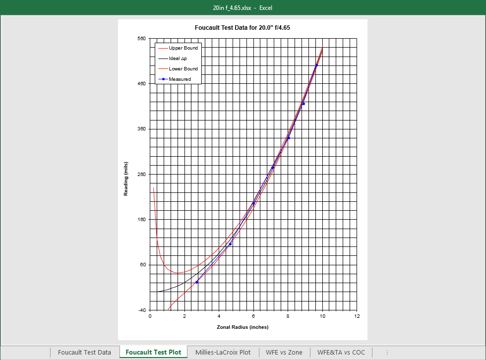
This is a plot of the Foucault test data for a 20 inch f/4.65
mirror completed in 1997. All you need to do is enter the diameter of the mirror, the f/#, and
the number of zones. The test mask is computed for you and you enter the measured data for
each zone. The upper and lower bounds for the Rayleigh criteria are then computed and plotted.
The optimum Center of Curvature (COC) is automatically calculated to minimize the maximum
absolute transverse aberration, and the results are plotted.
M I L L I E S - L A C R O I X
.
P L O T
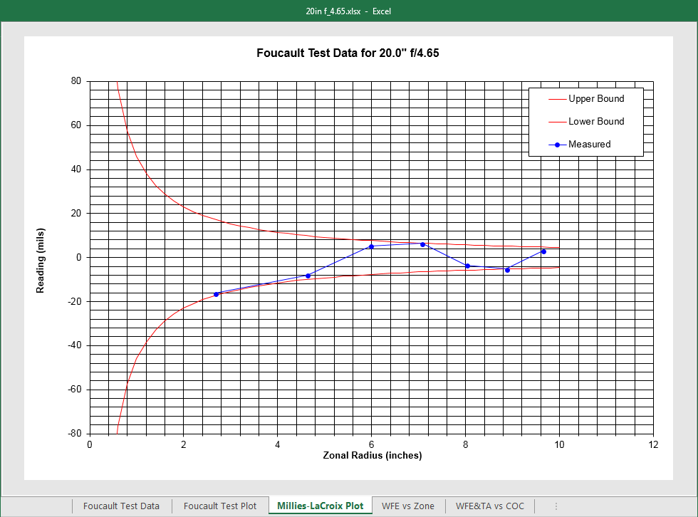
The Millies-LaCroix plot is the same as the Foucault
test data plot, except that the parabola has been subtracted out. This makes it easier
to see the deviation from ideal, especially for the outer zones where the test limits
are very tight.
W A V E F R O N T
.
E R R O R
.
P L O T
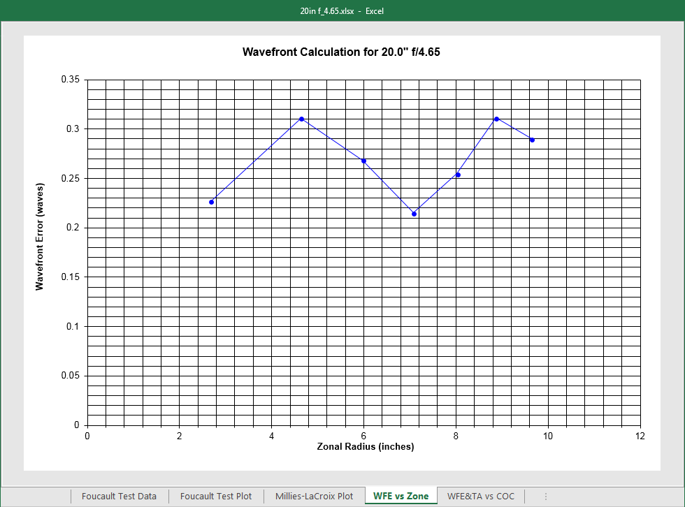
This plot shows the wavefront error versus the zonal radius for the
mirror. It is automatically calculated and plotted.
W A V E F R O N T
.
E R R O R
.
A N D
.
T R A N S V E R S E
.
A B E R R A T I O N
.
P L O T
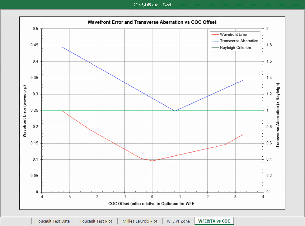
This plot shows wavefront error (WFE) and transverse aberration as functions of Center of Curvature offset. For this plot, zero offset is the COC which gives minimum
wavefront error. You can visually see the overlap region for the mirror where the Rayleigh criterion
is satisfied and the wavefront error is less than one quarter wave simultaneously. For this mirror,
the Rayleigh critierion is met just at an offset of about -0.8 mils; fortunately the wavefront error
is about 1/10-th wave at that point. This plot is also automatically generated.